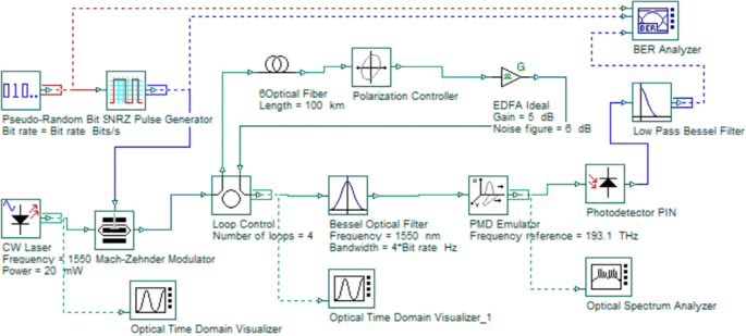

The parameters such as bit error rate (BER), quality factor (QF), and eye diagram have been investigated at the receiver end. We have analyzed dispersion compensation using dispersion compensating fiber (DCF) and fiber Bragg grating (FBG) techniques for different fiber lengths.

OptiSystem Tutorials - Volume 1 Optical Communication System Design Software Version 7. In our work, we are using OptiSystem, version 13.0 (Optiwave) for performance analysis of different compensation techniques. View Test Prep - ELCT1001STUDY GUIDEVolume1 from ELCT 1001 at German University in Cairo. By using OptiSystem software and MATLAB, variant types of dispersion compensation techniques used in optical fiber communication have been analyzed. Recent advancement in telecommunication services demands higher bandwidth which can be achieved by lowering the dispersion effect, i.e., pulse spreading. Due to this effect, the system bandwidth decreases. When signal or light pulse is transmitted by the optical fiber, it suffers from some loss due to the attenuation and dispersion. Transmitter, receiver, and amplifier design.In optical fiber, communication signal can be transmitted through one place to another by optical fiber in the form of pulses.We proposed more than 75+ optisystem projects. It is a special type of fiber used to compensate for signal dispersion b negative value of the dispersion coefficient. It is mainly encountered in a multichannel DWDM system in which a single channel system subject to self-phase reduction.


The simulation of optical soliton propagation was run for fiber length of one soliton period, z0 3.9482km, z 10km, and z 20km. It is the result of interaction among vibrating atoms in the crystal lattice and optical waves. Besides, PMD tab option from optical fiber component properties need to be selected, Birefringence type was changed to Deterministic and the Differential Group Delay was set to 0 ps/km as shown in figure 10.They are channel power reduction, increased dispersion, increased channel spacing, and fiber photon power peak reduction. It processes optical power from one channel to a multi-channel system that is spilled over into the adjacent channel.We implement the following methods in optisystem as, Four-wave mixing (FWM) It is composed of photoelectric detectors, filters & demodulators.Applicable for high capacity, long-distance optical fiber communication due to tremendous bandwidth.We mainly implement this DWDM system for M.Tech projects composed of, Transmitter The receiver converts distorted & attenuated weak optical signal output from fiber-optic lines to electric signals. The transmitter’s role is to convert the electrical signal into optical form & launch the result optical signal into an optical fiber. We provide this DWDM technology from Springer paper as,Īn optical communication system is composed of a transmitter, communication channel & receiver.


 0 kommentar(er)
